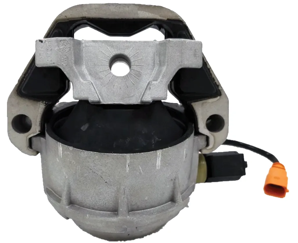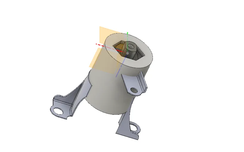
A hydraulic engine mount looks simple from outside, but every part of it is chosen with a purpose. Here is how the design is worked out: from the load it must carry, to the rubber hardness, to the materials, to the computer simulation that checks it before anything is made.
Step 1: define the job
The design assumes a maximum vertical load of 1000 kgf (about 9800 N). That covers an engine of around 200 kg plus the extra forces from vibration and driving. The rubber must not deflect by more than 3 cm: more than that and the engine moves too much and the mount can no longer isolate vibration. But it must not be too hard either, or it would pass noise and vibration straight into the cabin.
Step 2: find the right rubber hardness
The rubber part is divided into four segments, and each one behaves like a spring: F = K × x (force equals stiffness times deflection). The stiffness of each segment depends on the area the force acts on, the rubber’s Young’s modulus and its volume. The four segments came out at:
- K1 = 223.8
- K2 = 92.33
- K3 = 249.55
- K4 = 283.53
Combining them for a 3 cm limit at 9800 N gives a required Young’s modulus of about 7.46 MPa. Reading that against a Shore A hardness chart for elastomers gives a rubber hardness of about 75 Shore A.
Step 3: choose the materials
| Part | Material | Why |
|---|---|---|
| Rubber | Neoprene | Good ageing and oil resistance; Young’s modulus 8 MPa, tensile yield about 20 MPa |
| Connecting support | Aluminium alloy | Light and strong (yield about 280 MPa); bonded to the rubber and carries the engine bracket |
| Outer body | Structural steel | Strong enough to take the constant load (yield about 250 MPa) and resistant to rust when coated |
Several candidate materials were compared for the support and the body before these were selected.
Step 4: check it by simulation
Before any part is made, each one is loaded in ANSYS under a 3 kN force to see how it deforms and where the stress builds up.
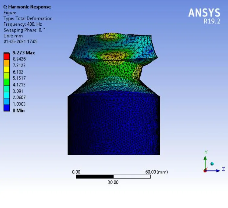
For the rubber, the highest equivalent stress was about 3.1 MPa against a tensile yield of roughly 20 MPa, with a minimum factor of safety of about 6.4. A frequency response (harmonic) analysis from 0 to 400 Hz was also run, since at low frequencies the rubber alone is responsible for isolating vibration.
Step 5: does the simulation match the real thing?
| Method | Force | Deflection |
|---|---|---|
| Simulation | 2000 N | 21.76 mm |
| Physical test | 2000 N | 23 mm |
The two agree to within about 5%, which gives confidence in both the model and the test. The design was then assembled and simulated as a whole in Fusion 360.
The takeaway
A good engine mount is the result of many small decisions: the rubber’s hardness, the shape that lets it move freely but grip tightly, the strength of the metal parts and the bond between them. It is exactly this kind of engineering that goes into every rubber-to-metal part we make at TechNix.
This article is based on the B.E. Mechanical Engineering project “Design, Fabrication and Analysis of Engine Mountings” by Bhavya Madhani, Devesh Parwal, Manraj Chandhok and Rhys Rodrigues, guided by Prof. Prashant Frank Crasta.